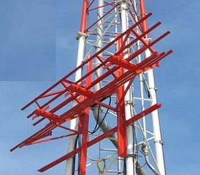


The glide path antenna consist of 6063T6 ultra corrosion resistant architectural anodized aluminum alloy and marine grade stainless steel mounting hardware. The antenna is supplied with international orange color powder coating finish.
The glide path antenna assembly consists of number of collinear dipoles mounted in front of a corner reflector, which together form the shaped horizontal and vertical patterns of the antenna.
Radiating elements of glide path antenna are sealed in fiberglass rarome to minimize environmental effects.
The entire RF distribution/combiner system of glide path antenna as well as the integral monitor are constructed using low loss, phase stable, semi-rigid coaxial cable which provides less sensitivity to environmental changes.
Glide Path Antennas are used to provide vertical guidance to aircraft during approach and landing of an aircraft under instrument fight rules.
The Glides Path Antennas are designed to withstand 200 Km/Hr wind, temperature range of -40oC to 70°C, and 95% humidity. All elements are sealed in fiberglass enclosure.
The GSP series glide path antennas has been designed and manufactured by us to provide highly accurate guidance information to an approaching aircraft while permitting increased flow of aircraft traffic in the vicinity of the GP tower.
Electrical Specifications:
Frequency Range: 328-336MHz.
Forward Gain: 10 dBi
Bandwidth: Entire 328-336MHz Band (No Tuning Required)
Impedance: 50 Ohms
Elevation Beamwidth: 80 Degrees
Azimuth Beamwidth: 23 Degrees
VSWR: 1.3:1
Power Handling Capacity: 100 Watts
Input Termination: N-Female
Mechanical Specifications:
Materials: 6063T6 Aluminum Alloy
Mounting Hardware: Stainless Steel
Wind Rating: 200Km/Hr.
Overall Length: 2.3 Meters
Overall Width: 0.5 Meter
Overall Height: 0.80 Meter
Gross Weight: 15 Kgs.
Finish: Powder Coated Orange
Environmental Specifications:
Operating Temperature: (-)30 to +70 Degrees Celsius
Storage Temperature: (-)40 to +80 Degrees Celsius
Humidity: 0 to 95% RH
Please contact us for complete technical datasheet in .pdf format.